Ford Five Hundred: Steering Wheel Controls Intro

In this post about my car, I'll discuss how I can use the analogue signal from the steering wheel buttons with an Arduino. The steering wheel controls are a simple voltage ladder, and we can program the Arduino to read the voltage and determine which button is being pressed.
Wiring
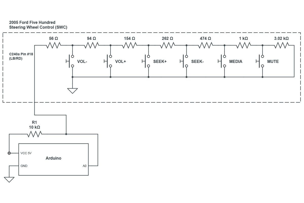
The SWC+ wire (light blue/red) from the steering wheel is available at pin 18 on connector C240a (24 pin on the back of the radio). Using a pull-up resistor, connect the SWC+ wire to an analogue input on the arduino.
Demo Sketch
int sensorPin = A0;
int sensVal = 0;

void setup() {
  Serial.begin(9600);
}

void loop() {
  sensVal = analogRead(sensorPin);

  if (sensVal > 0 && sensVal < 12) {
    Serial.print("VOL - :");
  }
  if (sensVal > 12 && sensVal < 16) {
    Serial.print("VOL + :");
  }
  if (sensVal > 27 && sensVal < 33) {
    Serial.print("SEEK + :");
  }
  if (sensVal > 47 && sensVal < 55) {
    Serial.print("SEEK - :");
  }
  if (sensVal > 87 && sensVal < 97) {
    Serial.print("MEDIA :");
  }
  if (sensVal > 167 && sensVal < 175) {
    Serial.print("MUTE :");
  }
  Serial.println(sensVal);

  delay(1000);
}
This Arduino sketch will measure the value of the analogue pin every 1000 milliseonds and print out the button being pressed (with the value it measured, for fine-tuning) on the serial console.
Taking Things Further
In a future post, I plan on exploring how to redirect the analog signal to the Arduino whenever we want to read the value to determine a button press. Since the radio is connected to the MS-CAN bus, this should be trivial. The button detection code can also be optimized further with some tips from the Ignorant of Things blog.